Quad Configurations Diamond or Square?
The two most popular configurations are the Diamond and Square. From a performance perspective there is no difference, in fact the element configuration may have many different shapes such as circular, triangle (Delta Loop), or rectangular. The key criteria is that the loop length must be nominally one wave length and the elements have to be symmetrical about a line through the feed point and bisecting the structure. Polarity is determined by were the feed point is located. On the bottom for horizontal and on the side (rotated 90deg) for vertical.
At Cubex Quads we use both configurations depending mostly on the desired band and other physical or mechanical considerations. Our large HF arrays are typically configured in the square or box and our smaller VHF (2m / 6m) and the EXPO series are Diamond configuration. The ARRL Antenna Book states that the diamond design is a superior mechanical design because the sloping element wires will shed water, thus reducing potential ice loading. We take issue with that premise, in fact we think it can be shown that the square is stronger and no more susceptible to ice loading then the diamond configuration and more importantly, it will support ice loads better.
Allow me to elaborate on our premise – first consider that the damaging stress for most spreader arms is not compression (the force down the axis of the arm) but the bending moment. I think it can be argued that when it is cold enough to freeze rain, an exposed element wire is colder and promotes freezing and therefore there is no run-off regardless of the angle. Considering this worst case that all element wires, regardless of orientation, will collect equal amounts of ice load; the Square configuration with it two supporting arms will be stronger.
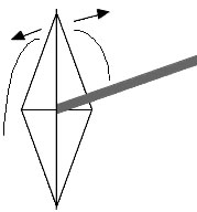
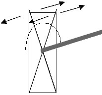
Looking at the two figures below, visualize that the element wires above the boom are ice coated. If we assume that the 45 deg. sloping lines of the diamond collects less ice than horizontal lines, it follows that the two vertical parts of the square configuration will collect even less ice. Assuming that the ice load factor for the diamond sloping elements are each 0.5, (a total of 1). So in the diamond configuration this ice load of 1.0 is supported by only one arm or a 1:1 support ratio.
In the square case assume the horizontal wire element load is 1.0 and the two verticals are each 0.25 for a total of load of 1.5. Therefore with the square we have an Ice Load of 1.5 but with TWO arms resisting the fore and aft motion for a support factor of 2 to 1.5 or 33% stronger! This analysis can be refined, but I think it makes the point why we at Cubex Quads believe the square or box configuration is superior for large HF arrays. As an added benefit, the turning radius is smaller!
-We welcome alternative analyses-


Design Considerations of the Cubical Quad Antenna (feeding the quad)
In the design of Cubical Quad antennas there are several competing goals or constraints that control the final results. Three important ones are Forward Gain, Front to Back ratio and Source Impedance. Other factors are material related – boom length and number of elements. Variations in the above parameters are modified by the choice of the number of elements, their dimensions and element spacing. Unfortunately the final result is both a compromise and an “optimization” to achieve certain goals and fit both mechanical and cost considerations.
One of these variables is the Source Impedance – At Cubex Quads we strive to design for either 50 ohm or 112.5 ohm source impedance. This allows common element location and the resulting equal physical spacing for all bands. We do not find any advantage to the so called “boomless” or optimized design and there may even be some disadvantages to that approach. One disadvantage is the boomless quad requires longer spreader arms, and the compound angles add even more structural stress under icing conditions.
The result of the Cubex Quads approach is that the higher frequency bands (10m, 12m, and 15m ) exhibit higher source impedance’s averaging around 100 ohms. This allows a simple 75 ohm 1/4wave series transformer (matching cable) to transform the terminating impedance to about 50 ohms giving a good match for that band.
The feeding of each band with separate feed-lines is the preferred method offering the following benefits:
- Broader bandwidth
- Deeper side nulls
- Virtually no power limitations
This approach does require separate runs of coax and series matching cables from the antenna feed points to a Remote Antenna switch.
Cubex Quads offers either 1/4 wave or 3/4 wave 75-ohm Matching cable sets for 10, 12, 15, 17, 20, 30 and 40 meters.
3/4 wave cables will reach to a mast mounted antenna switch. 1/4 wave cables may require 50 ohm extensions to reach the mast mounted switch.

